UAE Shops - Established in 2002
عربى
Numeric Water Level Indicator with Display
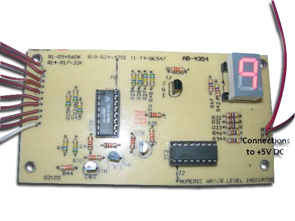
Most water level indicators are equipped to indicate and detect only a single level. The Numeric Water Level Indicator implemented here can indicate up to nine such levels and displays the level no. on a seven segment display. Simulating 10-90% levels in 10% increments. Hence, not only is the circuit capable of cautioning a person that the water tank has been filled up to a particular level, it can also indicate that the water level has fallen below the minimum level. This is particularly important in appliances such as the desert cooler where there is a danger of motor-burnout when the water is used up. This circuit exploits the simple fact that water is a good conductor of electricity. The placement of nine probes (having connections to the circuit) at different heights inside the water tank determines the nine different detectable levels. When the water reaches a particular height in the tank; the seven segment display shows the corresponding level no., digit 9 representing the “tank full” condition and digit 0 representing the “tank empty” condition. The Numeric Water Level Indicator employs a simple mechanism to detect and indicate the water level in a tank or any other container. The level sensing is done by a set of nine probes which are placed at nine different levels on the tank walls (with probe9 to probe1 placed in decreasing order of height, COM probe is placed on the base of the tank). Basically, level9 represents the “tank full” condition while COM represents the “tank empty” condition. When the tank is empty, all the inputs to the priority encoder 74HC147 (IC1) remain high, as a result its output also remains high. Since these outputs are inverted and fed as inputs to the decoder driver CD4511 (IC2), all inputs to IC2 are low. The seven segment display correspondingly shows the digit 0, indicating that the tank is empty. When the water reaches level1 (but is below level2), pin11 (A0) of IC1 is pulled to ground and the output generated at pin9 (Y0) of IC1 also becomes low. After inversion, the bits fed to the input pins of IC2 are 0001 (DCBA). Hence, the corresponding digit displayed by the seven segment display is 1. The similar mechanism applies to the detection of all the other levels. When the tank is finally full, all inputs to IC1 become low and all its outputs also go low. This causes all the inputs to IC2 to go high and hence the display shows a 9, thereby indicating a “tank full” condition. Learning: Application of the Priority Encoder IC 74HC147 Application of the BCD to Seven Segment Decoder IC CD4511 (for driving seven segment displays) Brand: Kits'n'spares, Marketed by: Kits'n'spares


