UAE Shops - Established in 2002
عربى


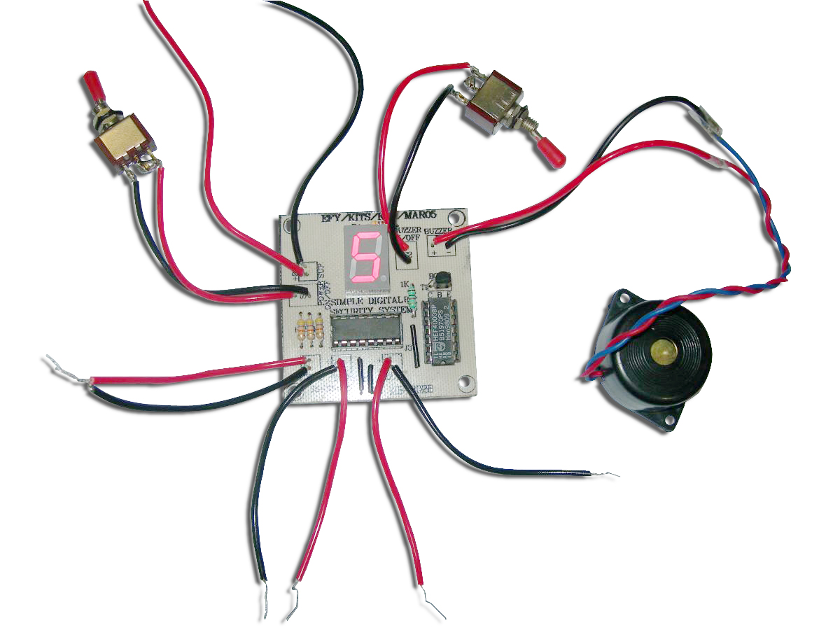
Simple Digital Security System
A reliable security system is a necessity in todays day and age in order to protect one’s home from burglars and intruders. The Simple Digital Security System can be used as a watch-dog by installing simple sensing loops around one’s building. The system is based upon an enameled copper wire loop circuit. The circuit also consists of a seven-segment display that indicates the room no. where the intrusion has taken place, these numbers being assigned by the user through the circuitry. At the time of an intrusion, the loop breaks and the buzzer generates an alarm while the seven-segment display shows the room number been intruded. The Simple Digital Security System explained here can check intrusions for a maximum of three rooms. There are three loops in the circuitry namely loop1, loop2 and loop4. Hence, for example, if loop1 (corresponding to room1) is broken, the display shows a 1. Similarly, if loop2 or loop4 is broken, the numbers 2 and 4 are displayed respectively. However, if two or more loops are broken simultaneously then the sum of the loop numbers are displayed on the seven segment display. It is for this reason that the loops are NOT labeled as 1, 2 and 3. Because, in such a case a 3 being displayed by the seven-segment could be construed as simultaneous intrusions in room1 and room2 or an intrusion in room3, thereby leading to confusion and chaos. Number of ICs used: 2 The circuit employs a simple mechanism to implement a security system and hence ensures protection from intruders. Of the four inputs that the decoder driver provides, three (A, B, C) are used I connection with the three loops (loops 1, 2 and 4). The fourth input D is grounded and not used. The output of the CD4511 (decoder driver-IC1) is connected to the display input such that it shows the number of the broken loop (or the room that has been broken-into). When all the loops are closed i.e. the rooms are secure, the display shows the digit 0. On the other hand, if all loops are broken, then it displays the digit 7 (since 1+2+4=7). The status of each of these loops is also read by the CD4000 (IC2), whose output determines the sounding of the buzzer. Consider the following cases: 1. Secure Premises: When all the loops are closed and the premises are secure, each of the three inputs to the NOR gate of IC2 is 0. Upon applying the NOR logic, the output is 1 (HIGH) which is further applied to the inverter and hence, the final output obtained is 0 (LOW). This low signal when applied to the base of the transistor causes the transistor switch to remain OFF and the buzzer does not send off a beep, thereby indicating that no intrusion has taken place. 2. Intrusion: When a loop is broken or two or more loops are broken, the NOR gate will have non-zero inputs and hence the output will be a 0 (LOW). This when applied to the inverter becomes a 1 (HIGH) which switches the transistor to the ON state. Consequently the buzzer beeps, indicating the occurrence of an intrusion/break-in. Learning: Application and implementation of the BCD to 7-segment latch decoder drivers CD4511. Application of the dual 3-input NOR gate and inverter IC CD4000. Connections to a seven segment display and its uses. Brand: Kits'n'spares, Marketed by: Kits'n'spares