UAE Shops - Established in 2002
عربى
Heat sensitive switch
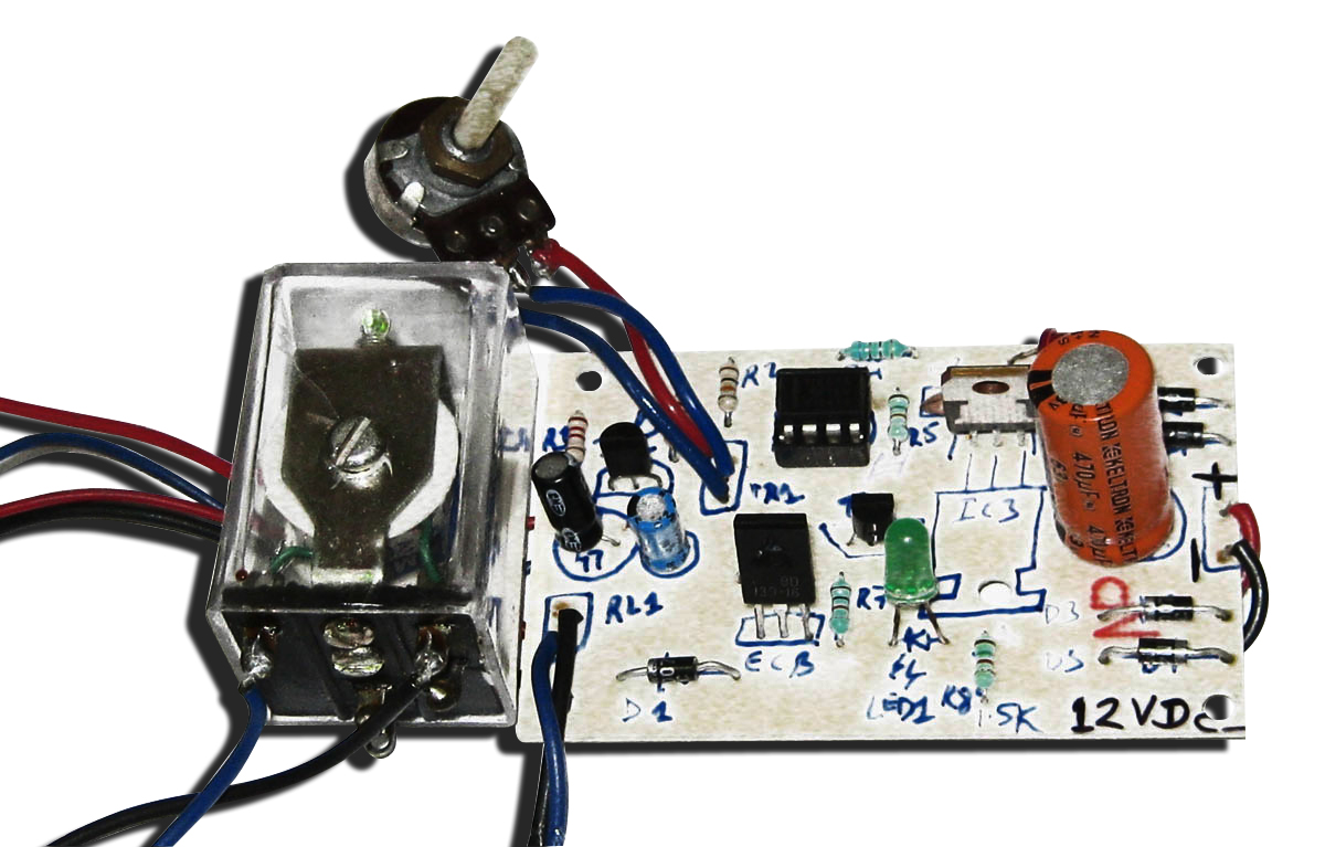
The purpose of the Heat Sensitive Switch is to detect the ambient temperature and bring into effect a switching action for an appliance or a device. The Heat Sensitive Switch implemented here is a simple temperature sensing circuit employing the LM35 temperature sensor IC. This circuit also provides a mechanism to set a threshold temperature value such that the switching action will be performed only above this set temperature. Thus, the ambient temperature can trigger the circuit to switch on an appliance or any other load connected to it. Number of ICs used: 3 The heart of the Heat Sensitive Switch is the LM35 temperature sensor that converts temperature (in Celsius) into a voltage signal. This voltage output is applied to the non-inverting input (pin 3) of the comparator (CA3130 or IC2). The inverting input (pin2) of this comparator is connected across the positive supply rails via a voltage divider network formed by potentiometer VR1. Since the wiper of potentiometer VR1 is connected to the inverting input of IC2, the voltage presented to this pin is linearly variable. This voltage is used as the reference level for the comparator against the output supplied by IC1 (LM35). If the non-inverting input of IC2 receives a voltage lower than the set level, its output goes low (approximately 650 mV). This low level is applied to the input of the load-relay driver comprising NPN transistors T1 and T2. The low level presented at the base of transistor T1 keeps it in cut-off. Since T2 receives the forward bias voltage via the emitter of T1, it is also in the cut-off mode. Hence, relay RL1 is in a de-energized state, keeping mains supply to the load ‘off’ as long as the temperature at the sensor is low. Conversely, if the non-inverting input receives a voltage higher than the set level, its output goes high (approximately 2200 mV) and the load is turned ON. This happens when IC1 is at a higher temperature and its output voltage is also higher than the set level at the inverting input of IC2. So the load is turned on as soon as the ambient temperature rises above the set level. Capacitor C3 at this pin helps iron out any ripple that passes through the positive supply rail to avoid errors in the circuit operation. By adjusting potentiometer VR1 and thereby varying the reference voltage level at the inverting input pin of IC1, the temperature threshold at which the relay get energized, can be set. As this setting is linear, the knob of potentiometer VR1 can be provided with a linear dial calibrated in degrees centigrade. Therefore any temperature level can be selected and constantly monitored for turning on/off a device or appliance. Learning: Application of the precision temperature sensor IC LM35. Implementation and application of the operational amplifier IC CA3130 as a comparator Brand: Kits'n'spares, Marketed by: Kits'n'spares


